- HOME
- Technology & Trends
- Network diagrams explained: A practical guide for IT and infrastructure teams
Network diagrams explained: A practical guide for IT and infrastructure teams
- Last Updated : June 30, 2026
- 12 Views
- 9 Min Read

It's 2 a.m., and your company's customer portal has suddenly gone offline.
Alerts are firing. Users are reporting issues. Engineers are jumping between dashboards, cloud consoles, and monitoring tools, trying to identify the root cause.
Is the issue coming from a firewall rule? A failed server? A Kubernetes service?
Everyone is asking the same question:
"How is everything connected?"
In modern IT environments, the answer isn't always obvious. Networks span data centers, cloud platforms, containers, remote devices, and countless applications. Without a clear view of how these components interact, troubleshooting becomes slower, documentation becomes harder to maintain, and infrastructure grows increasingly difficult to manage.
This is where network diagrams become invaluable. In this guide, you'll learn what a network diagram is, why it's important, the different types of network diagrams, and best practices for creating effective network documentation.
What is a network diagram?
At its core, a network diagram is a visual representation of your IT infrastructure. It shows how devices, servers, applications, cloud services, and other network components connect, communicate, and work together, making even complex environments easier to understand.
Think of a network diagram as a map for your IT infrastructure.
Just as a city map shows roads, intersections, and destinations, a network diagram shows how devices, systems, and services connect and communicate within a network. Instead of helping you navigate streets, it helps you understand how data moves between users, applications, servers, and cloud environments.
Why are they important?
Network diagrams play a critical role in helping organizations manage, secure, and scale their infrastructure effectively.
Improve network visibility
Getting a complete view of your infrastructure becomes much easier when everything is visualized in one place. Teams can quickly understand how devices, systems, and services interact, making it easier to identify dependencies, bottlenecks, and potential issues.
Simplify troubleshooting
When network issues occur, engineers need to identify the root cause quickly. A well-maintained diagram helps teams trace connections, locate affected systems, and reduce mean time to resolution (MTTR).
Strengthen security planning
Visualizing network architecture makes it easier to identify vulnerabilities, review access controls, and ensure security measures are implemented correctly across the environment.
Support infrastructure documentation
Accurate diagrams serve as a reliable source of documentation for onboarding new team members, conducting audits, and maintaining operational continuity.
Enable better capacity planning
As organizations grow, network diagrams help teams assess existing infrastructure, plan upgrades, and design scalable architectures that support future requirements.
Facilitate cloud and hybrid network management
Modern IT environments often span multiple cloud providers, data centers, and remote locations. Network diagrams help teams understand how these distributed systems connect and communicate with one another.
How do network diagrams work?
Network components
Every network diagram starts with the components that make up the network.
These components can include physical hardware, virtual resources, cloud services, and end-user devices. Here are some common elements you can find.
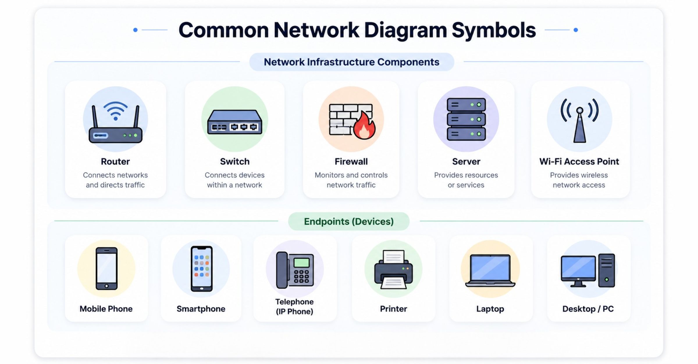
Each component is represented using standardized symbols, making it easier to read and understand across teams.
For example, a diagram for a cloud application might show a load balancer routing traffic to application servers, which then communicate with a database hosted in a separate environment.
Connections and data flow
A network isn't just a collection of devices—it's the connections between them that matter.
Network diagrams use lines, arrows, and links to show how information travels from one component to another. These connections can represent:
Physical cables
Wireless connections
VPN tunnels
Internet links
Cloud networking routes
Understanding data flow helps teams identify potential bottlenecks, optimize performance, and quickly locate the source of connectivity issues.
For instance, if users are unable to access an application, a network diagram can help engineers trace the path between the user, firewall, load balancer, application server, and database to determine where communication is failing.
Network dependencies
Modern IT environments often contain hundreds, or even thousands, of interconnected systems. A network diagram doesn't just show which components are connected. It reveals how they depend on one another.
For example, an application server may rely on a database to retrieve data, while a load balancer depends on multiple servers to distribute traffic efficiently. Understanding these dependencies helps IT teams assess the impact of failures, troubleshoot issues faster, and plan infrastructure changes with confidence.
Types of network diagrams
A single network can be viewed in different ways depending on the task at hand. An engineer replacing hardware doesn't need the same level of detail as a network architect designing a new infrastructure or a security team reviewing traffic paths.
That's why diagrams are created from different perspectives. Some focus on the physical infrastructure, others on communication patterns, while some illustrate the overall structure of the network.
Choosing the right type ensures the information needed is provided without unnecessary complexity.
Physical network diagrams
These diagrams document the hardware that makes up a network and where it's located. They're commonly used during network deployment, maintenance, and infrastructure upgrades, where knowing the placement of devices and cable connections is essential.
A physical network diagram typically includes:
Routers
Switches
Firewalls
Servers
Network cables
Wireless access points
End-user devices
Because these diagrams reflect the physical layout of a network, they're particularly useful for equipment installation, hardware inventory, and troubleshooting connectivity issues caused by faulty devices or cabling.
Logical network diagrams
While physical diagrams focus on infrastructure, logical diagrams focus on communication. They illustrate how traffic flows across the network, regardless of where devices are physically located.
A logical network diagram may include:
IP address ranges
VLANs
Subnets
Routing paths
VPN connections
Security zones
Cloud networks
These diagrams help administrators understand how systems communicate, making them valuable for network design, performance optimization, security planning, and troubleshooting.
Quick note: It's common for organizations to maintain both a physical and a logical network diagram for the same network.
The physical diagram supports infrastructure management, while the logical diagram provides insight into communication patterns and network behavior.
Common network topologies
A network diagram doesn't just show the components of a network—it also reflects how the network is designed. That's where network topology comes in.
Network topology refers to the arrangement of devices and communication links within a network. Understanding the underlying topology helps IT teams create accurate network diagrams, identify potential points of failure, optimize performance, and design infrastructure that can scale as business needs evolve.
The following are the most common network topologies used in modern IT environments.
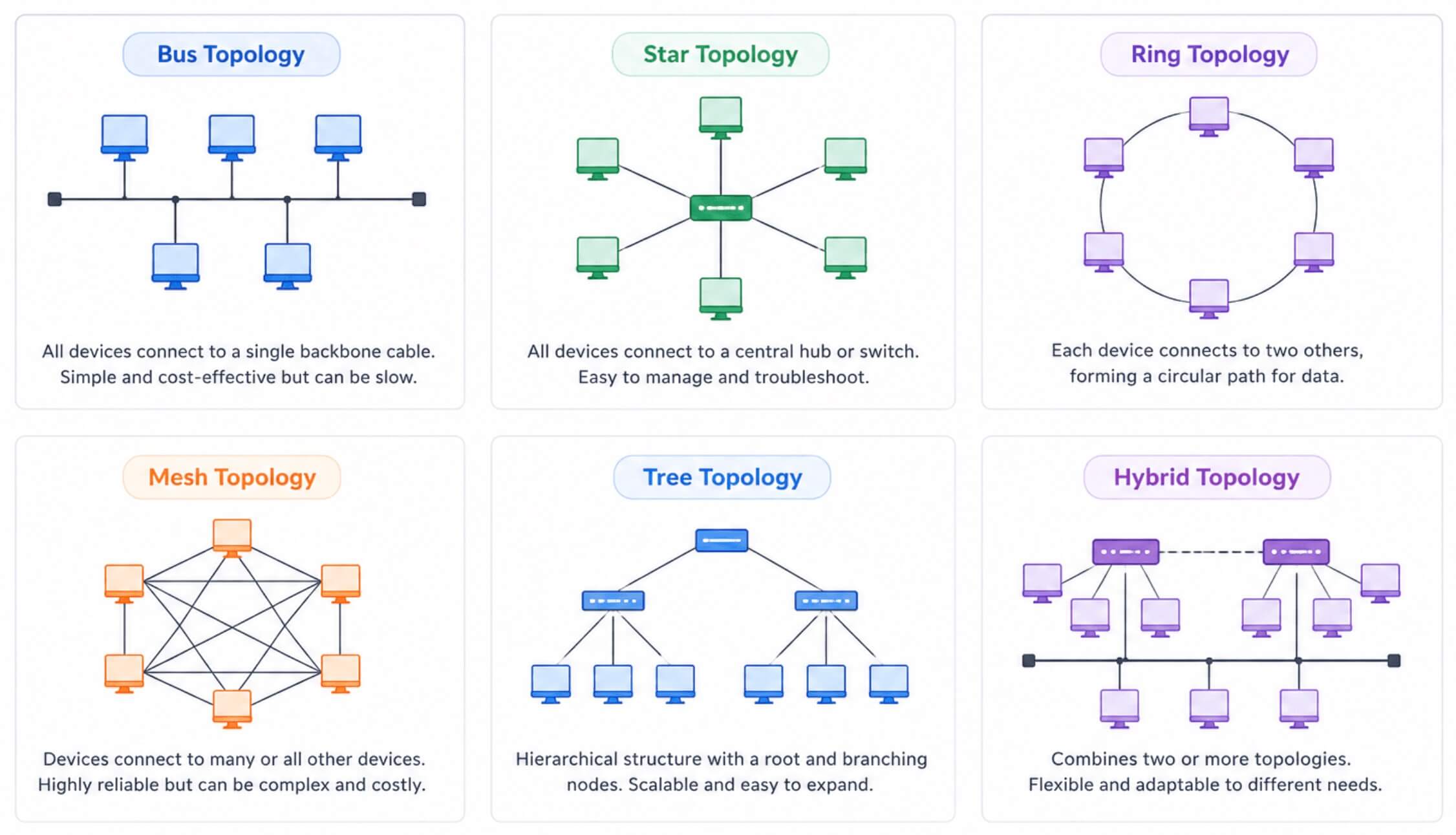
Star topology
Every device is connected to a central device, such as a switch or hub. Since each device has its own dedicated connection, issues affecting one device typically don't impact the rest of the network.
Star topology is the most widely used network layout today because it's easy to deploy, manage, and troubleshoot.
Best for: Office networks, enterprise LANs, Modern Ethernet networks
Bus topology
All devices share a single communication cable, known as the backbone. Data travels along this shared cable until it reaches the intended destination.
Although bus topology is simple and cost-effective, it's rarely used in modern networks because the backbone represents a single point of failure. As networks grow, performance can also degrade due to increased traffic.
Best for: Small networks and legacy network environments
Ring topology
Each device is connected to two neighboring devices, creating a continuous loop. Data travels around the ring until it reaches its destination.
While ring topology offers predictable data transmission, it's less flexible than newer network designs and is primarily found in specialized industrial or legacy systems.
Best for: Industrial control systems and legacy networking environments
Mesh topology
Devices are interconnected through multiple communication paths instead of relying on a single connection.
This built-in redundancy makes mesh topology highly reliable and resilient, making it a preferred choice for environments where downtime isn't an option.
Best for: Data centers, wireless mesh networks, mission-critical infrastructure
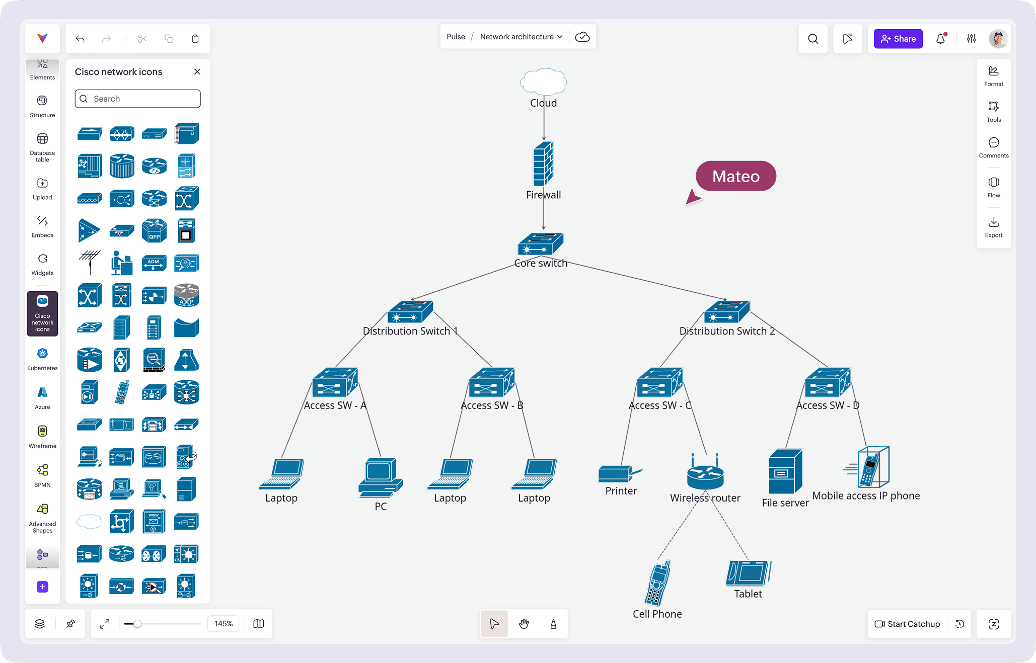
Tree topology
Multiple star networks are organized into a hierarchical structure connected through a central backbone. This approach makes large networks easier to organize, manage, and expand over time.
Tree topology is commonly used by organizations with multiple departments, campuses, or branch offices that require a scalable network architecture.
Best for: enterprise networks, campus networks, large organizational infrastructures
What network topologies do modern enterprises use?
While all the topologies provide the foundation for network design, modern enterprise networks rarely rely on a single topology. Instead, organizations typically use hybrid topologies that combine multiple designs to meet different operational requirements.
For example, an enterprise might use:
Star topology within individual office locations for easy management and troubleshooting.
Tree topology to organize departments, campuses, or branch offices into a hierarchical structure.
Mesh topology between critical data centers to ensure high availability and redundancy.
Cloud and hybrid environments make these architectures even more common. As organizations adopt platforms like AWS, Azure, and Kubernetes, network designs evolve to support distributed workloads, remote users, and multi-cloud connectivity.
As a result, enterprise network diagrams often represent a combination of physical infrastructure, logical communication paths, and multiple network topologies.
How to create an effective network diagram
Creating a network diagram isn't just about placing icons on a canvas. The quality of your diagram depends on the planning that happens beforehand. Before you begin, consider the following questions.
What's the purpose of your diagram?
Begin with a clear objective. Network diagrams created for documentation, deployment planning, troubleshooting, or security audits each require a different level of detail.
Who is the diagram for?
A network administrator may need hardware details and cable connections, while a cloud architect may be more interested in routing, subnets, and service dependencies. Design your diagram around its audience.
How much detail should you include?
One of the biggest mistakes is trying to include everything. Instead, include only the information needed for the task. A high-level architecture diagram and a detailed troubleshooting diagram can represent the same network but serve entirely different purposes.
How will you keep it updated?
A network diagram quickly loses its value if it doesn't reflect the current infrastructure. Establish a process to review and update diagrams whenever significant changes are made to the network.
Network diagram Kits for modern infrastructure
Building a network diagram from scratch can be time-consuming, especially when working with complex IT environments. Network diagram kits provide a ready-to-use collection of industry-standard shapes, symbols, and components, making it easier to create accurate, consistent, and professional diagrams.
Whether you're documenting an office network or designing a cloud-native architecture, the right kit helps you visualize infrastructure faster while following established networking conventions.
General network kit
The general network diagram kit includes the essential symbols required to document traditional network infrastructures, such as routers, switches, firewalls, servers, wireless access points, and endpoints. It's ideal for creating office, enterprise, and campus network diagrams.
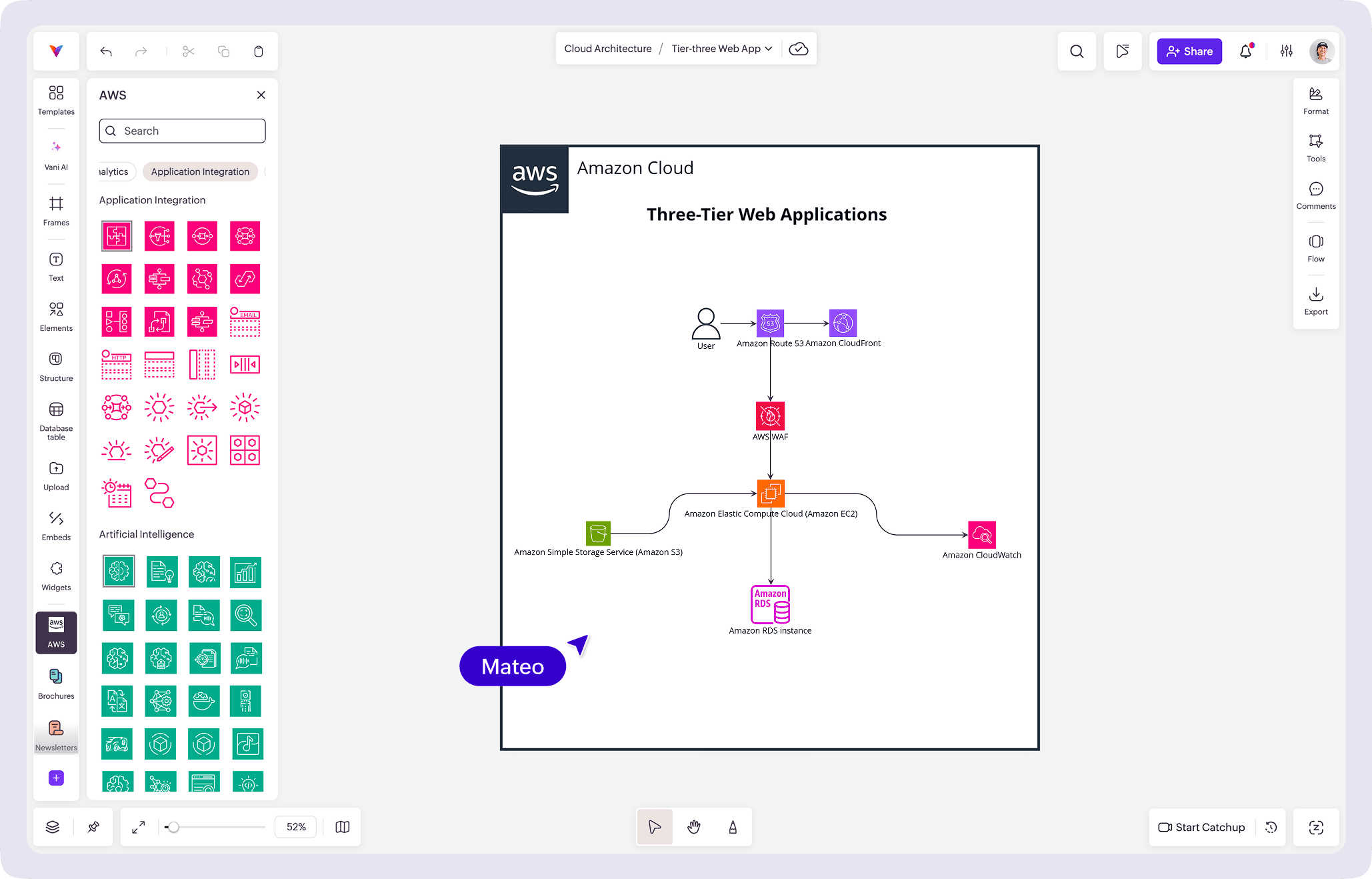
AWS kit
The AWS network diagram kit includes AWS-specific architecture icons and components, allowing teams to accurately visualize services such as Amazon VPC, EC2, Elastic Load Balancing, RDS, and more.
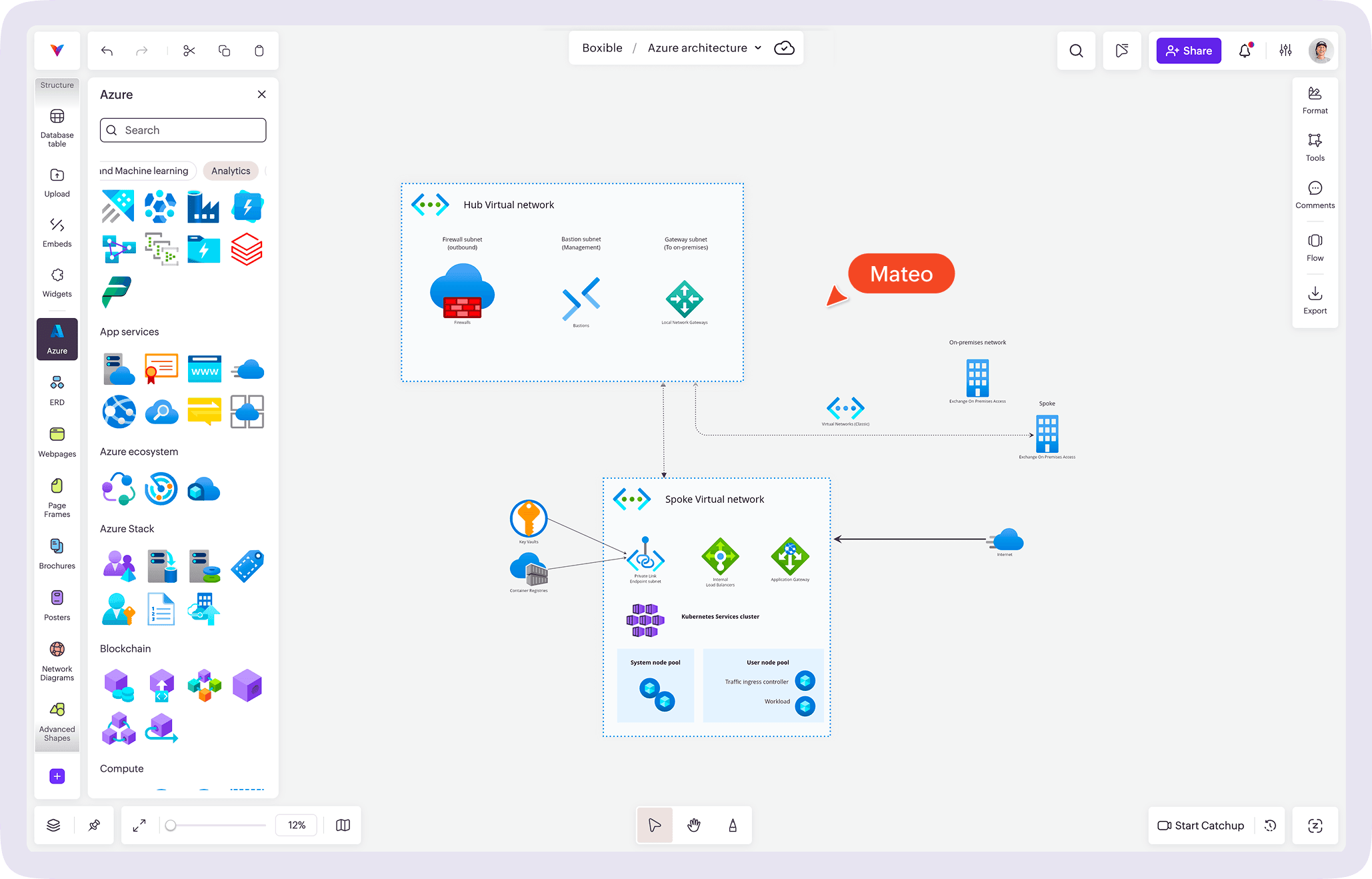
Azure kit
The Azure network diagram kit contains Microsoft Azure icons and networking components for documenting Virtual Networks (VNets), virtual machines, VPN gateways, Azure Firewall, and other Azure services.
Google Cloud (GCP) kit
The GCP network diagram kit provides Google Cloud Platform icons for creating diagrams that represent VPC networks, Compute Engine instances, Cloud Storage, load balancers, and other GCP resources.
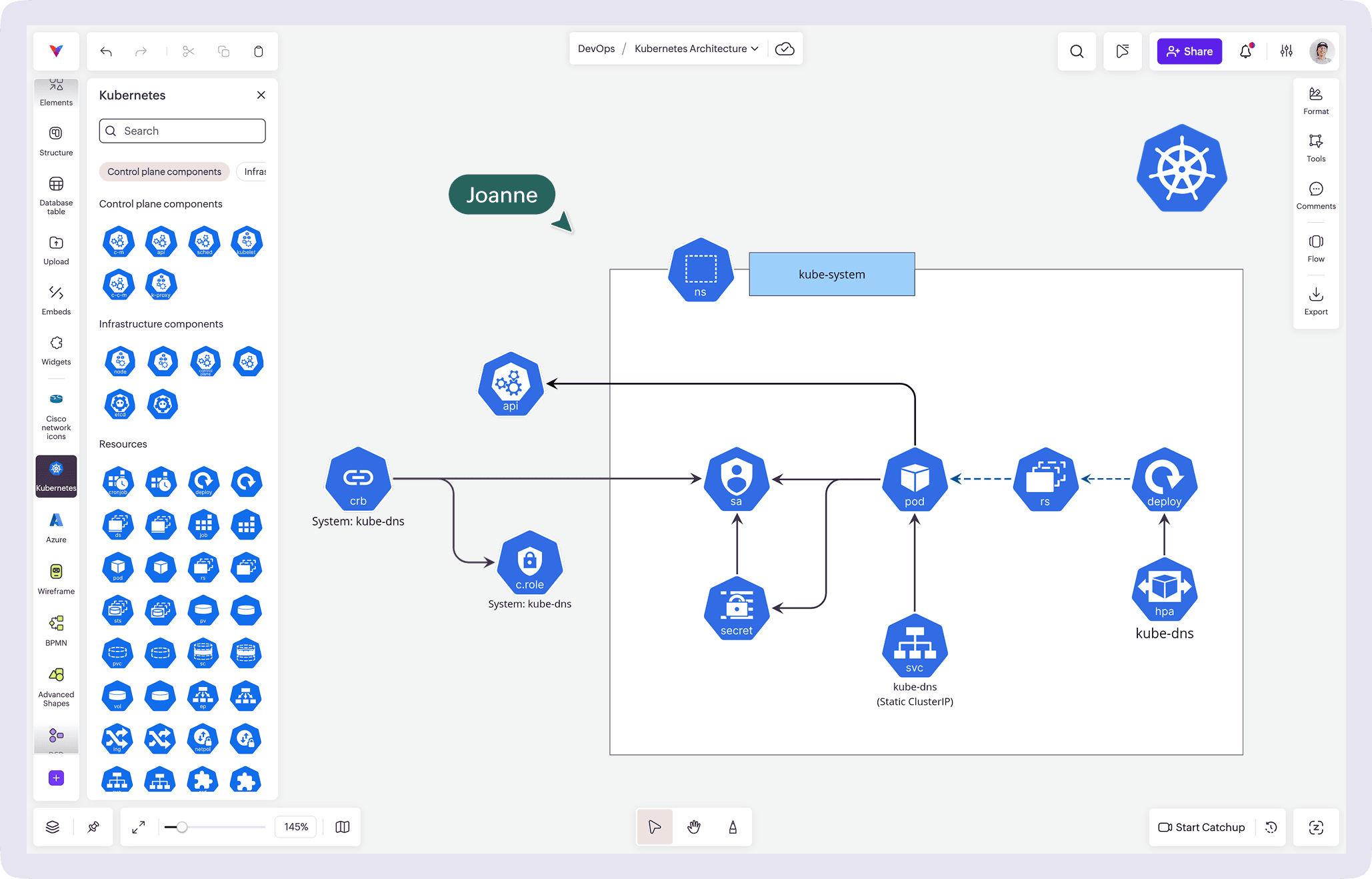
Kubernetes kit
The Kubernetes network diagram kit includes symbols for clusters, nodes, pods, services, ingress controllers, and other Kubernetes resources, helping teams document containerized applications and distributed workloads.
Cisco kit
The Cisco network diagram kit features Cisco-specific networking symbols for routers, switches, firewalls, wireless controllers, and other enterprise networking devices, making it easier to create standardized Cisco infrastructure diagrams.
Using the right network diagram kit not only speeds up the diagramming process but also ensures consistency across teams, making network documentation easier to maintain as your infrastructure evolves.
Final Thoughts
A network diagram is really one of those things you don't think about until you really need it. Then suddenly it's the most useful document in the room.
Whether you're planning changes, onboarding teammates, or trying to untangle a mystery that started with "it was working yesterday," having a clear diagram can save a surprising amount of time and frustration.
So keep it simple, keep it updated, and most importantly, make it something your team will actually use.
Looking for a head start? Explore Vani's Kits for ready-to-use resources that help you visualize, plan, and collaborate on everything from network diagrams to cloud architectures and beyond.
Frequently asked questions
1. What is the difference between a physical and a logical network diagram?
A physical network diagram shows the actual hardware and physical connections in a network, including routers, switches, servers, and cables. A logical network diagram focuses on how data flows between devices, regardless of their physical location.
2. Which network topology is best for modern businesses?
The best topology depends on your network requirements. Star topology is the most common choice for its simplicity and reliability, while tree and hybrid topologies are ideal for larger, more complex networks. Mesh topology is best suited for environments that require high availability.
3. What symbols are commonly used in network diagrams?
Network diagrams typically include symbols for routers, switches, firewalls, servers, databases, cloud services, wireless access points, and end-user devices. Using standardized symbols makes diagrams easier to understand across teams.
4. How often should a network diagram be updated?
A network diagram should be updated whenever new devices are added, network configurations change, infrastructure is upgraded, or security policies are modified. Keeping diagrams current helps simplify troubleshooting and planning.
5. Why are network diagrams important for troubleshooting?
A network diagram provides a visual map of devices and their connections, making it easier to identify bottlenecks, locate failed components, understand traffic flow, and resolve connectivity issues more quickly.
6. Can network diagrams be used for cloud infrastructure?
Yes. Modern network diagrams can represent cloud environments such as AWS, Microsoft Azure, and Google Cloud Platform. They help visualize virtual networks, cloud services, security groups, load balancers, and hybrid infrastructure.
7. What's the difference between a network diagram and a network topology?
A network topology describes the structure or layout of a network, such as star, mesh, or bus. A network diagram is the visual representation of that structure and often includes additional details like devices, IP addresses, security components, and data flow.